Cisco C7200-I - Input/Output Controller - Control Processor Specifications Page 41
- Page / 192
- Table of contents
- TROUBLESHOOTING
- BOOKMARKS
- Configuration Guide 1
- CONTENTS 3
- Contents 4
- Document Revision History 9
- Audience 9
- Organization 10
- Document Conventions 10
- Note reader take note 11
- Warning Definition 12
- Attention 13
- Avvertenza 13
- Advarsel 14
- ¡Advertencia! 14
- Varning! 14
- Terms and Acronyms 15
- Related Documentation 16
- Obtaining Documentation 17
- Documentation Feedback 18
- Submitting a Service Request 20
- Physical Description 23
- Physical Description 24
- Power Specifications 25
- Software Requirements 26
- Cisco 7204VXR Overview 26
- 8 PWR OK LED 28
- Cisco 7206VXR Overview 29
- ORK PROCESSING ENGINE-300 31
- Field-Replaceable Units 32
- Field-Replaceable Units 33
- Component Location 37
- GIGABIT ETHERNET 0/1 38
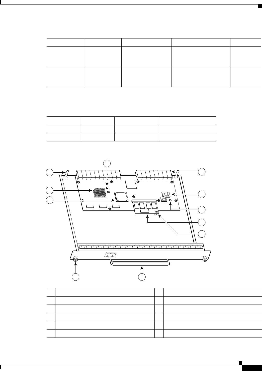
- Figure 1-8 NPE-400 41
- Figure 1-9 NPE-300 43
- Input/Output Controller 54
- C7200-I/O-GE+E 55
- C7200-I/O-2FE/E 56
- CPU RESET 57
- LED Descriptions 62
- NPE-G2 LEDs 63
- NPE-G1 LEDs 64
- LED Color Function 66
- Port Adapter Jacket Card 70
- 3 62 4 5 72
- 2 31 4 5 72
- Memory Size Product Number 75
- Functional Overview 76
- Functional Overview 77
- Environmental Monitoring 81
- NPE-175, NPE-225, NPE-300 82
- NPE-400, NSE-1 82
- NPE-100 or NPE-200 82
- Router(boot)# 83
- Reporting Functions 84
- Preparing for Installation 87
- Site Requirement Guidelines 89
- Site Requirement Guidelines 90
- Rack-Mounting Guidelines 91
- Specification Minimum Maximum 93
- Power Connection Guidelines 94
- Plant Wiring Guidelines 94
- Site Log 99
- . This guide contains 101
- OL-5013-08 102
- Cisco 7200 104
- XVR eries 104
- Series VXR 105
- TOKEN RING 106
- Statement 70 120
- Specification Description 121
- Class 1 laser product 125
- Statement 1008 125
- Class 1 LED product 125
- 12345678 130
- Fast Ethernet MII Connections 133
- Figure 3-27 MII Port 134
- Signal Direction Description 136
- Adapter DTE M/F Pins 139
- Connecting Power 141
- Connecting AC-Input Power 142
- Connecting DC-Input Power 142
- Connecting Power 143
- Basic Configuration 145
- Configuring ATM Interfaces 154
- 1.1.1.30 156
- GBIC port 0/2 160
- Troubleshooting Overview 167
- Action Yes No 168
- Identifying Startup Problems 169
- I/O Controller LEDs 170
- NPE-G1 or NPE-G2 LEDs 171
- Port Adapter Jacket Card LEDs 172
- Port Adapter LEDs 172
- System Bootup Banner 172
- APPENDIX 177
- Bits 0–3 178
- Bit 10 and Bit 14 180
- Bit 11 and Bit 12 180
© 2020, manymanuals.com. All rights reserved. | 2.816 s |
 Manymanuals.com
 Manymanuals.de
 Manymanuals.fr
 Manymanuals.it
 Manymanuals.pl
 Manymanuals.cz
 Manymanuals.es
 Manymanuals-pt.com
Comments to this Manuals